Introduction
The traditional data science process starts with raw data and ends up to the creation of a model. That model is then usually moved into daily production. Integrated Deployment allows not only the model but all the associated preparation and post-process steps to be identified and reused in production in an automatic way, and without having to shift between different tools.
The Integrated Deployment nodes allow you to capture the fragments of the workflow needed for running in a production environment, the model or library itself as well as the data preparation. These captured subsets are saved automatically as workflows with all the relevant settings and transformations and can be run at any time, both on KNIME Analytics Platform for model validation and on KNIME Server for model deployment.
In this guide we will explain how to use the nodes that are part of the KNIME Integrated Deployment Extension, as well as other useful nodes that allow the use of this feature in different environments.
|
You can access more material about Integrated Deployment on this website section. |
Installation
You can install KNIME Integrated Deployment Extension from:
-
KNIME Hub: go to the KNIME Integrated Deployment Extension page on KNIME Hub. Here, drag and drop the squared yellow icon to the workbench of KNIME Analytics Platform.
-
KNIME Analytics Platform: go to File → Install KNIME Extensions… in the toolbar and find KNIME Integrated Deployment under KNIME Labs Extensions or type Integrated Deployment in the search bar.
For more detailed instructions refer to the Installing Extensions and Integrations section on the KNIME Analytics Platform Installation Guide.
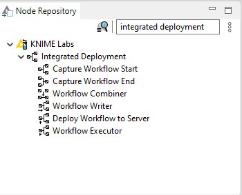
Now the nodes are available in the node repository under KNIME Labs → Integrated Deployment, as shown in Figure 1.
Create a workflow
In this section we will explain how to build a workflow, capture some fragments, and finally combine them into a new workflow. In this new workflow you can also store the input and output data.
|
All the workflows shown in this section are available on KNIME Hub. |
Capture fragments of a workflow
With the Integrated Deployment nodes you can capture the fragments of the workflow that you need. To do this you can use Capture Workflow Start and Capture Workflow End nodes, as shown in Figure 2.

Capture Workflow Start node marks the start of a workflow fragment to be captured. Capture Workflow End node marks the end of a workflow fragment to be captured. The entire workflow fragment within the scope of these two nodes is then available at the workflow output port of the Capture Workflow End node. Nodes that have out-going connections to a node that is part of the scope but are not part of the scope themselves are represented as static inputs but not captured.
In Figure 3 an example of the corresponding captured workflow is shown. For an explanation on how to generate the captured workflow please refer to the Export a captured workflow section.

Configuration of the Capture Workflow End node
Input data
You can store input data with your captured workflow. These data will be used by default when running the captured workflow unless you provide a different input. Storing input data will add data to the Container Input (Table) node in the captured workflow. In this way data are saved with the workflow when writing it out or deploying it to KNIME Server and are available when executing the workflow locally or on KNIME Server.
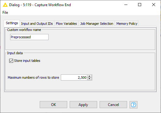
To store input tables, right-click the Capture Workflow End node and choose Configure… from the context menu. In the node configuration dialog that opens, shown in Figure 4, check Store input tables option. Here you can also choose the maximum number of rows to store with the captured workflow.
Add or remove input or output ports in Capture Workflow nodes
In Capture Workflow Start and Capture Workflow End nodes you can choose to have how many input and output ports of different types as necessary, as shown in Figure 5.

-
To add input ports:
-
Click the three dots in the left-bottom corner of the Capture Workflow Start/End node
-
Choose Add Captured workflow inputs port from the context menu that opens
-
Choose the port type from the drop-down menu in the window that opens
-
-
To remove input ports:
-
Click the three dots in the left-bottom corner of the Capture Workflow Start/End node
-
Click Remove Captured workflow inputs port.
-
Rename captured workflow and input/output ports
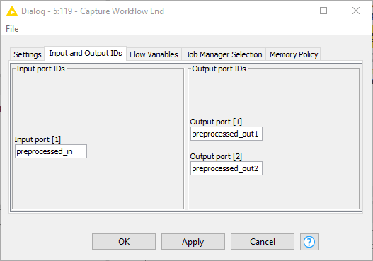
In the Capture Workflow End node you can change the name of the captured fragment of the workflow, as well as inputs and output ports. Right-click the Capture Workflow End node and choose Configure… from the context menu. In the node configuration dialog that opens, you can give the captured workflow a custom name in the Settings tab, as shown in Figure 4. To rename input and output ports instead go to Input and Output IDs tab, as shown in Figure 6.
Combine captured workflow fragments
You can capture more than one fragment of the workflow with multiple couples of Capture Workflow Start/End nodes and combine all the different captured fragments into a single new workflow. To combine the different captured fragments use the Workflow Combiner node. The Workflow Combiner node can take as many as necessary workflow models as input and generates a combined captured workflow. To add or remove input model ports click the three dots in the left-bottom corner of the Workflow Combiner and choose Add(Remove) workflow model port in the context menu. An example with the relative captured workflow is shown in Figure 7.

Input/output port mapping
Free output ports from one workflow fragment are connected to the free input ports of the consecutive workflow fragment. However the pairing of the output and input ports can be manually configured.
Workflow fragments connected to consecutive ports to the Workflow Combiner node form a pair. For each pair you can select if and how to connect the outputs of the first workflow fragment to the inputs of the consequent workflow fragment. By default the inputs of each workflow fragment are automatically connected with the outputs of the predecessor. In case the default pairing cannot be applied, e.g. because of a non-matching number of inputs and outputs or incompatible port types, the node requires manual configuration in order to be executed.
If the default configuration is not applicable or you want to manually configure it, right-click the Workflow Combiner node and choose Configure… from the context menu to open the node configuration dialog, shown in Figure 8
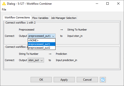
Here, you can choose the pairing manually. For example, the first pane in
Figure 8 shows the pairing between a workflow fragment
(Preprocessed) that has two data output ports preprocessed_out1 and
preprocessed_out2 with a workflow fragment (String To Number) connected to
the consequent port of the Workflow Combiner node.
From the drop-down menu you can choose to connect any or <NONE> of the output
ports of the Preprocessed workflow fragment to the input port of the
String To Number workflow fragment.
Please, note that only compatible port types are shown and can be connected.
Save and execute a captured workflow
In this section we will explain how to save, deploy and execute the captured workflow, in a local or remote file system or on KNIME Server.
|
All the workflows shown in this section are available on KNIME Hub. |
The captured workflow can be:
-
Written locally or to a file system using the Workflow Writer node
-
Deployed to KNIME Server with the Deploy Workflow to Server node
-
Directly executed with the Workflow Executor node
Export a captured workflow
Export a captured workflow to local workspace
You can write the newly captured workflow locally or to a remote file system using the Workflow Writer node. Connect the Workflow Writer node editor to the output workflow model port (squared solid black port) of the workflow you want to write, i.e. the output port of Workflow Combiner node or Capture Workflow End node, as shown in Figure 9.

Now, you can open the Workflow Writer node configuration dialog, shown in Figure 10.
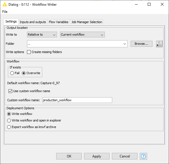
Here, you can setup:
-
Output location: You can choose to write a captured workflow with a specific path relative to the local file system, a specific mountpoint or relative to current mount point, current workflow or current workflow data area.
-
Workflow: You can choose to overwrite the workflow if one with the same name already exists in the chosen location or to fail. You can also give the captured workflow a custom name.
-
Deployment options: You can choose between writing the workflow, writing the workflow and opening it in explorer or export the workflow as
knwfarchive.
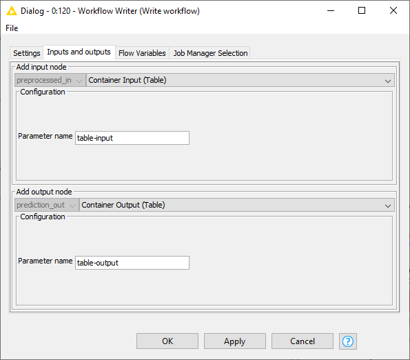
In the Inputs and outputs tab of the Workflow Writer node configuration dialog, shown in Figure 11, you can also choose to add input and output nodes to a captured workflow.
Export a captured workflow to a remote file system
You can also connect the Workflow Writer node to a remote file system, e.g. SharePoint, Amazon S3, Google Cloud Storage. First you need to authenticate to the chosen remote file system and then connect to it. Then, right-click the three dots in the left-bottom corner of the Workflow Writer node and from the context menu choose Add File System Connection port. A squared solid cyan connection port will appear and it can be connected to the relative output file system connection port of the chosen remote file system connector node. An example workflow with SharePoint remote file system is shown in Figure 12.

Now the Workflow Writer node configuration dialog shows the remote file system in the Output location section of the Settings tab and you can choose to save the captured workflow into a location on that file system.
|
Please note that if you are writing to a remote file system the workflow can only
be written or exported as |
Deploy a captured workflow to KNIME Server
You can deploy a captured workflow to KNIME Server with the Deploy Workflow to Server node, following these steps:
-
Set up a connection to the server with the KNIME Server Connection node
-
Connect the KNIME Server Connection node to the Deploy Workflow to Server node via the squared solid light blue KNIME Server connection port
-
Connect the Deploy Workflow to Server node to the output workflow model port of the workflow you want to write, i.e. the squared solid black output port of Workflow Combiner node or Capture Workflow End node, as shown in Figure 13.
 Figure 13. An example workflow to deploy a workflow to KNIME Server
 -
Open the Deploy Workflow to Server configuration dialog, shown in Figure 14, by right-clicking the node and choosing Configure… from the context menu.
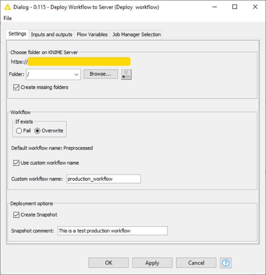 Figure 14. The Deploy Workflow to Server node configuration dialog
In the Deploy Workflow to Server node configuration dialog you can setup the following options:
-
Choose folder on KNIME Server: You can choose the folder on the server file system to which deploy the newly captured workflow.
-
Workflow: You can choose to overwrite a workflow if one with the same name already exists in the chosen location or to fail. You can also give the written workflow a custom name.
-
Deployment options: You can choose to create a snapshot and add an optional snapshot comment in order to keep track of the changes made to the workflow on the server.
In the Inputs and outputs tab of the Deploy Workflow to Server node configuration dialog, shown in Figure 15, you can also choose to add input and output nodes to the workflow. This will add Container Input/Output (Table) nodes to the captured workflow deployed to KNIME Server.
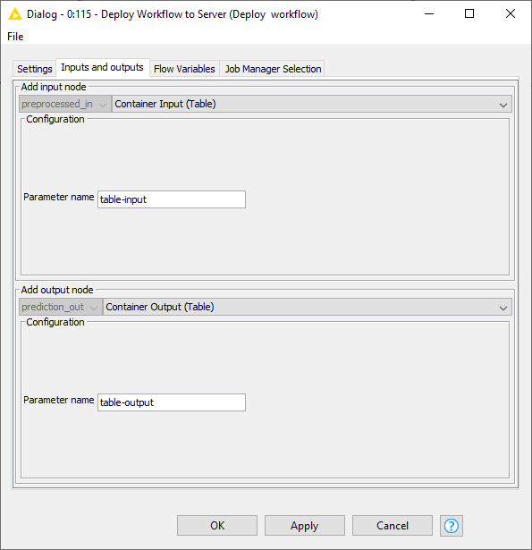
| If the captured workflow deployed to Server is executed on the Server (see Execute a captured workflow deployed to KNIME Server section) via Call Workflow node the Container Input/Output (Table) nodes are mandatory. |
Execute a captured workflow deployed to KNIME Server
You can execute a captured workflow:
-
On KNIME Server or on KNIME WebPortal
-
On KNIME Server from the KNIME Analytics Platform client. In this way you can also provide additional data in case you want to run the captured workflow on new data. To do this you can use a Call Workflow node, connected to the KNIME Server Connection node via the KNIME Server connection port. If needed, i.e. if no input data was stored with the captured workflow, input data have to be provided, as shown in Figure 16.
 Figure 16. An example workflow to execute the captured workflow from KNIME Server with some input data
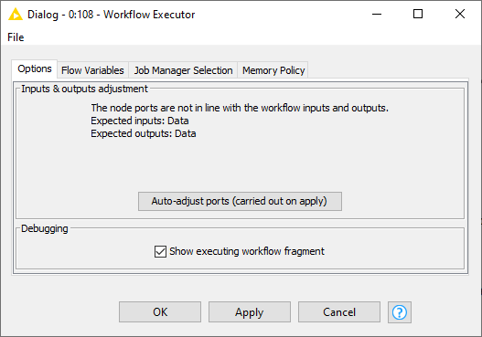
Execute a captured workflow locally
You can also execute the workflow locally by using the Workflow Executor node.
| The Workflow Executor node can only execute a workflow that is captured from the same workflow the Workflow Executor node is part of. |
The node ports match the input and output ports of the workflow. Connect the Workflow Executor node to the output workflow model port of the workflow you want to write, i.e. the output workflow model port of Workflow Combiner node or Capture Workflow End node, and, if needed, the input data port to a data table. An example is shown in Figure 17.

You can adjust the needed input and output ports to match those of the workflow to be executed by opening the node configuration dialog shown in Figure 18, and clicking Auto-adjust ports (carried out on apply).