
Control Your Workflow Logic
Introduction
Not all workflows have a static input and only one branch. Often, data are updated regularly, and some settings can be different from time to time. In other cases a workflow might have branches and a rule that determines which branch to follow.
In this guide, the tools available in KNIME Analytics Platform to control the flow in the needed direction are introduced.
In particular this guide explains how to:
- Parametrize settings using flow variables
- Repeat a part of the workflow for different inputs
- Define a rule to activate a branch
- Provide an error handling branch if node execution fails
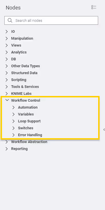
The nodes that come in hand here are shipped automatically with the KNIME Analytics Platform and do not require the installation of any extension. You can find these nodes in the node repository. Activate the Tree view and select the Workflow Control.
Flow variables
Flow variables are parameters with string, integer, double, arrays, or Path values. These parameters can be used to avoid manually changing settings within the nodes of a workflow when a new execution with different settings is required. Flow variables are available only for the downstream nodes in the workflow.
Creating flow variables
To create flow variables you have the following possibilities:
- Convert a table row into flow variables
- Export a node configuration as flow variable
- Use Configuration and Widget nodes
- Use Variable Creator node
- Combine or modify existing flow variables
The first two options are introduced in this section. The Widgets and Configuration nodes are explained in more details in the Components Guide. However, an example that makes use of this type of nodes in the context of creating a flow variable is available on KNIME Hub.
An example of the last option is the Rule Engine Variable node, which is introduced in the IF and CASE Switches section.
Converting a table row into flow variables
The Table Row to Variable node converts each column of the first row of a data table into a flow variable.
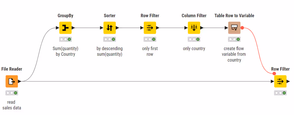
In this example, which is available on KNIME Hub, the Table Row to Variable node is connected to the following nodes:
- GroupBy node: Aggregates quantity by country
- Sorter node: Respectively group the original data by country, counting how many times an entry in the data corresponds to a specific country and sorts the data by descending quantity.
- Row Filter and Column Filter nodes: Prepare the data for the Table Row to Variable node by selecting only the first row according to the Sorter node only including the column country. This is necessary because the Table Row to Variable node takes a table as input and converts the first row to flow variables, discarding additional rows below.
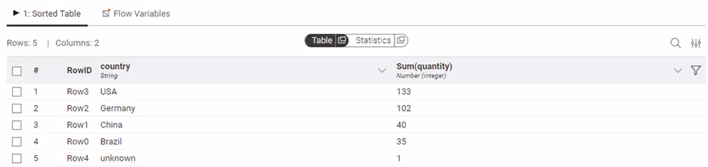
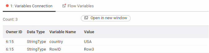
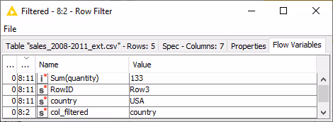
The output of the Table Row to Variable node is shown below. The three column names visible in the column "country" of the data table above are now the names of the flow variables, while the values of the first row ("RowID" and "USA") are the corresponding values of the flow variables, visible in the Value column of the table.
The output of the Table Row to Variable node is shown below. The three column names visible in the column "country" of the data table above are now the names of the flow variables, while the values of the first row ("RowID" and "USA") are the corresponding values of the flow variables, visible in the Value column of the table.
Exporting a node configuration as flow variable
Another option to create a new flow variable is to export a node configuration. You apply the flow variable to a subsequent node in its configuration dialog. In this case the flow variable acquires the same value used for the node configuration. The name for the flow variable is defined also in the node configuration dialog.
To export a node configuration that has a flow variable icon next to it follow these steps:
- Open the configuration dialog of the subsequent node, e.g. a Row Filter.
- Click the Add criterion button and filter for the column name that should be converted to a variable, "country" in this example.
- Next to the Value field, click the flow variable icon to overwrite it with a flow variable.
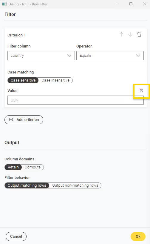
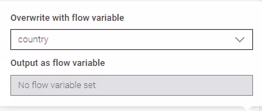
- In the dropdown menu, select the column name to be replaced with a flow variable, e.g., "country". Ensure that the whole workflow is executed, if the flow variable is not overwritten immediately.
- In the Output as flow variable field below, you can output your flow variable with a custom name at the output port of the node that you exported it to. You can read more on that in the Overwriting node configurations with flow variables section.
Some KNIME node configuration dialogs are not updated for KNIME Modern UI yet. The node configuration dialogs in Classic UI are described in the Classic UI configuration dialogs section below.
Using flow variables
Flow variable ports
The flow variable ports are red circles above each node. Every node has flow variable ports. You can make them visible by hovering over the node with your mouse cursor:
Overwriting node configurations with flow variables
In the previous section, we explained how to create flow variables. Here, we show how to use a previously created flow variable to configure a node.
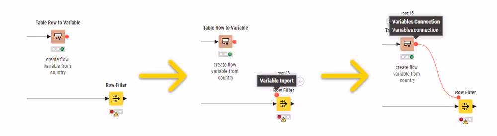
In case you want to use a flow variable you need to first connect the node where the flow variable is created to the following one. This is the node you want to use the flow variable in. S If the two nodes are not connected already via any other port, use the flow variable ports. You need to create the connection only once, then the transferred flow variables are available for all subsequent nodes in the workflow.
The process of overwriting a node configuration with a flow variable is similar to exporting it, as described above in Exporting a node configuration as flow variable.
To use a flow variable follow these steps:
- Open the configuration dialog of the node whose setting you want to overwrite via the flow variable. The flow variable icon is not always present in the node configuration dialog, but you can find it next to node configurations that are often overwritten by flow variables.
If the chosen configuration setting has a flow variable icon next to it, click it.
In the dropdown menu, select the column name to be replaced with a flow variable.
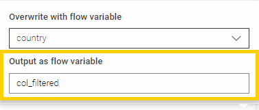
Below, in the Output as flow variable field below, you can output your flow variable with a custom name at the output port of the node that you exported it to. For example, the flow variable from the column "country" will be output as "col_filtered" in the example shown here:
Classic UI configuration dialogs
Some KNIME node configuration dialogs are not updated for KNIME Modern UI yet. In KNIME Classic UI you can also export a node configuration as flow variable. This is described in the following. Be aware that node configuration dialogs are in the process of being updated to KNIME Modern UI.
Exporting a node configuration as flow variable in Classic UI
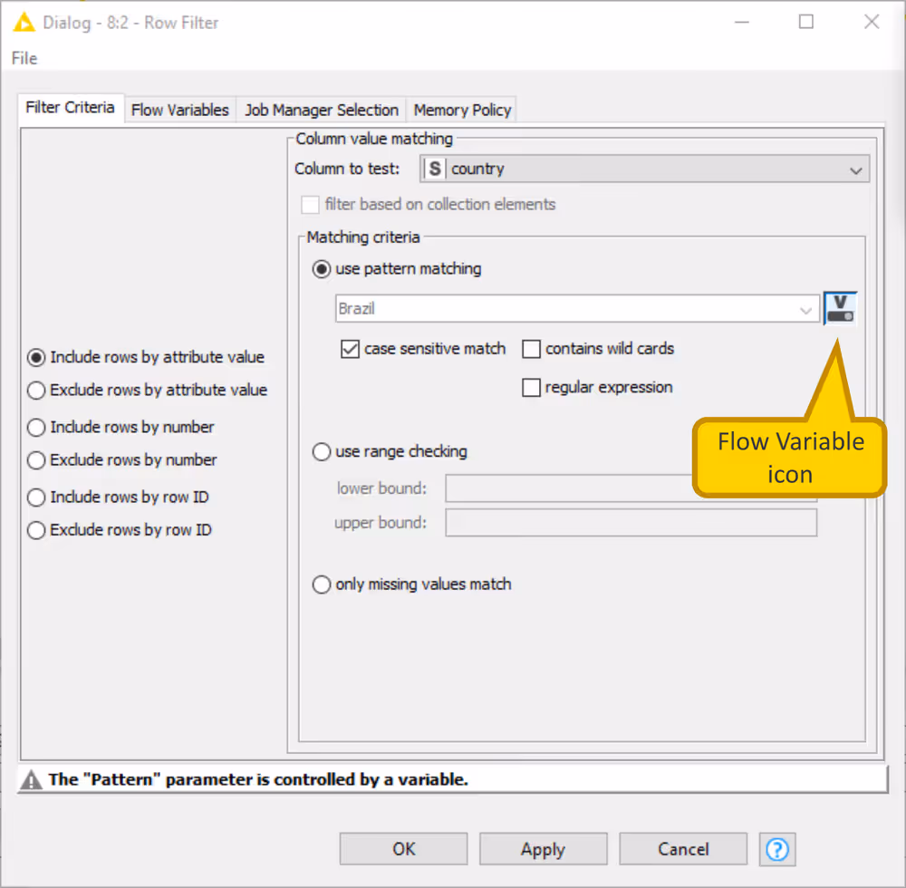
In the node configuration dialog some configuration options have a flow variable icon next to them. Consider for example the KNIME Classic UI configuration dialog of the Row Filter node. Next to the string pattern, click on the flow variable icon.
The node configuration dialog of the Row Filter node has been updated to KNIME Modern UI, as explained in Exporting a node configuration as flow variable.
In Classic UI, to export a node configuration that has a flow variable icon next to it, open the node configuration dialog and follow these steps:
Define the node configuration value in the corresponding field
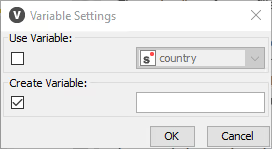
Click the icon and select Create Variable in the dialog that opens.
Write the flow variable name in the field that activates.
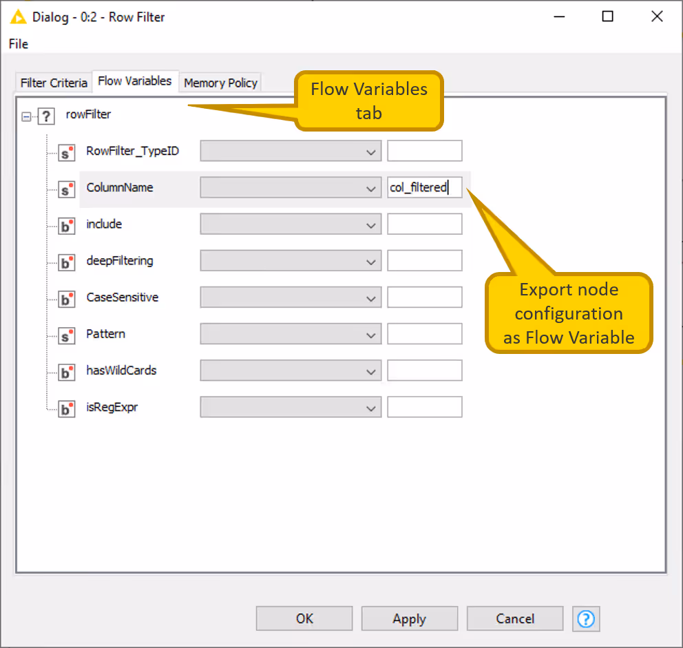
If there is no flow variable icon next to the setting to be exported, follow these steps:
Define the node configuration value in the corresponding field
Open the Flow Variables tab in the node configuration dialog
Write the flow variable name in the text field close to the drop-down menu in the row corresponding to the node configuration to export:
Now, the Flow Variables tab in the output table view of the node, shows the exported flow variable.
Overwriting node configurations with flow variables in KNIME Classic UI
Overwriting node configurations with flow variables in KNIME Classic UI is similar to the same procedure in Modern UI, described in in the section Overwriting node configurations with flow variables above. KNIME Classic UI has some intricacies described in the following.
Once in the configuration dialog of the node whose setting you want to overwrite via the flow variable, click on the flow variable icon. The flow variable icon is not always present in the node configuration dialog, but you can find it next to node configurations that are often overwritten by flow variables.
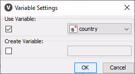
- If the chosen configuration setting has a flow variable icon next to it, click it and in the Variable Settings dialog that opens select Use Variable. Then select the flow variable from the drop-down menu:
 2. If the flow variable icon is not present, go to the Flow Variables tab, navigate to the chosen node configuration and select the flow variable from the drop-down menu:
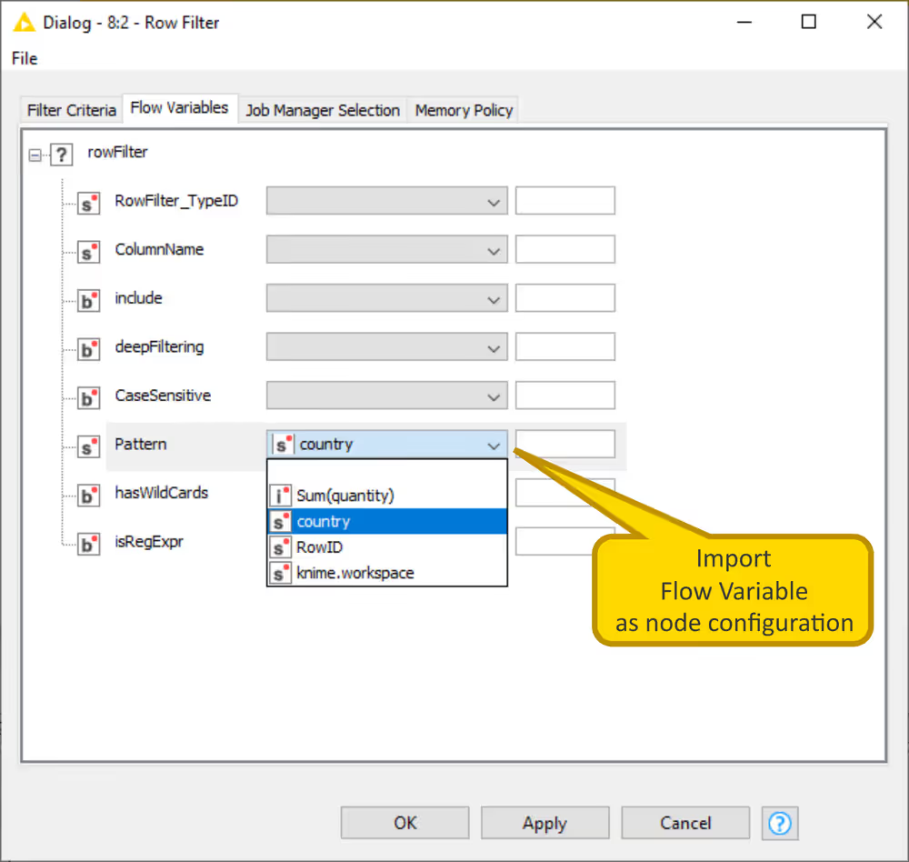
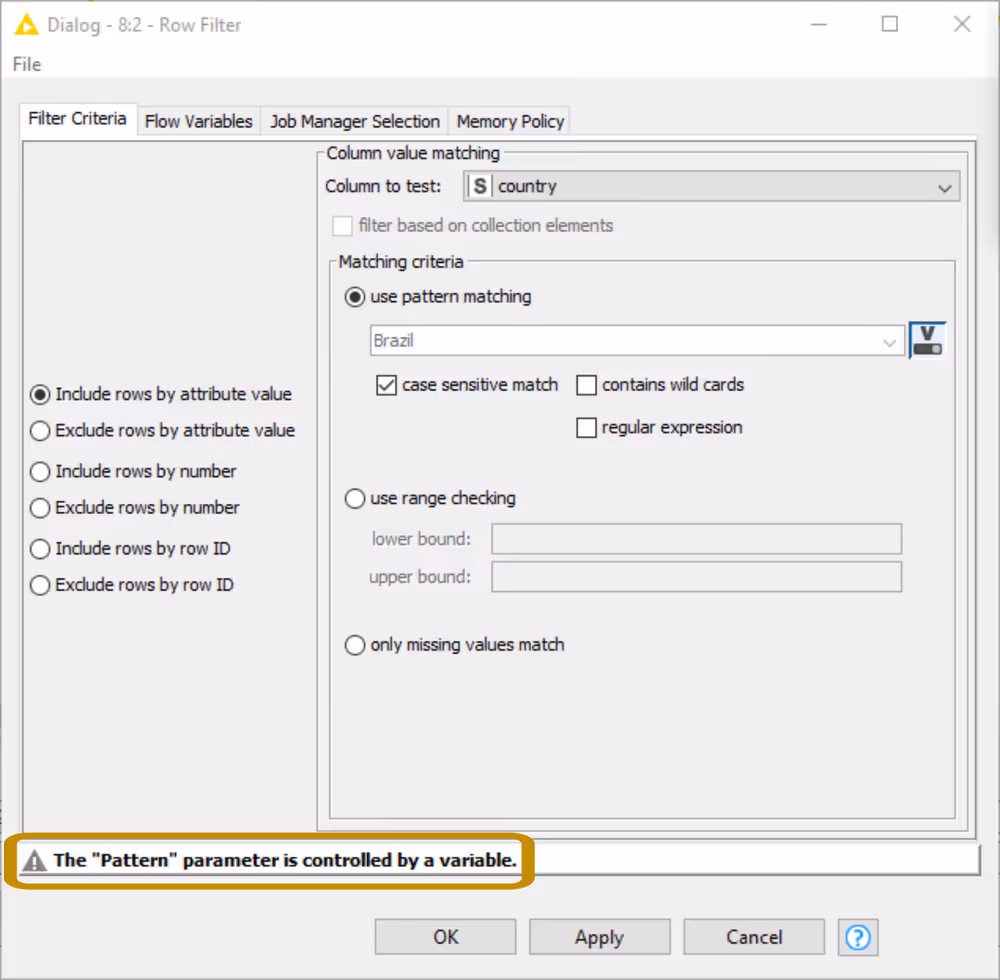
When you overwrite a node configuration with a flow variable, a warning message appears in the lower part of the node configuration dialog pointing out which node configuration is overwritten.
Loops
Loops iterate over a certain part of the workflow. Each iteration, a repeated procedure, has different input. What changes for each iteration can be a parameter value, dataset, subgroup of the same dataset, single column, or single row as flow variables.
Check out this video to understand how loops work in KNIME.
A loop in KNIME begins with a Loop Start node and ends with a Loop End node. The operations that are performed for each iteration are executed in the loop body. Generally, the Loop Start node is responsible for increasing the iteration counter and for sending the data to the loop body, which is then responsible for executing sub-workflow steps. After those are performed the Loop End node checks if the end condition is fulfilled, and if this is not the case the Loop Start node increases the counter and performs the loop body operations again. When the end condition is fulfilled, the Loop End node collects the data from the different iterations and the next step in the workflow is performed.
The loop in the figure below, which is available on KNIME Hub, is an example where the Chunk Loop Start node is used to iterate over a table, which contains ten rows filled with the letter A, created with the Table Creator node.
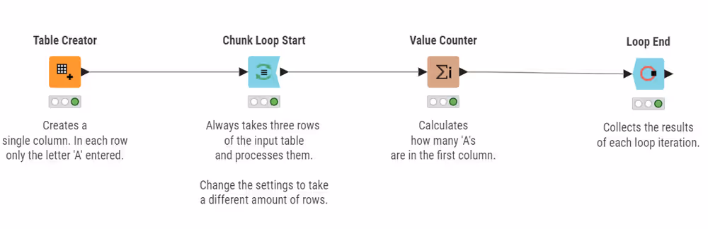
The Chunk Loop Start node takes three rows of the input table and sends a chunk of the data to the loop body, which is made of a Value Counter node. Finally, a Loop End node collects the results of each loop iteration and ends the loop when the condition of reaching the last row of the input data is fulfilled.
KNIME Analytics Platform provides different loop start and loop end nodes for different types of loops. You will find these nodes in the node repository by navigating to Workflow Control → Loop Support.
Loop start nodes
| Node Icon | Loop Start Node | Explanation |
|---|---|---|
 | Counting Loop Start | Triggers loop for a predefined number of iterations |
 | Chunk Loop Start | Splits data into consecutive chunks for each iteration. Either the number of chunks or the number of rows per chunk is defined. |
 | Column List Loop Start | Iterates over a list of columns |
 | Generic Loop Start | Together with the Variable Condition Loop End node it iterates until a certain condition is met |
 | Table Row To Variable Loop Start | Converts every row in a table into row variables and iterates over them |
 | Group Loop Start | Iterates over groups of data that are defined based on a condition |
 | Interval Loop Start | Increases a variable value for each iteration within a given interval |
 | Recursive Loop Start | Iterates over the output data table from the Recursive Loop End node by taking its output as input |
 | Recursive Loop Start (2 Ports) | Iterates over the two output data tables from the Recursive Loop End (2 ports) node |
Loop end nodes
| Node Icon | Loop End Node | Explanation |
|---|---|---|
 | Loop End | Concatenates the output tables from the different iterations |
 | Loop End (2 Ports) | Concatenates the output tables from each iteration into two separate tables when each iteration produces two output tables |
 | Loop End (Column Append) | After each iteration the output table is joined with the output table from previous iteration, collects the data column-wise instead of row-wise |
 | Recursive Loop End | Passes the output table from an iteration to a Recursive Loop Start node until either the maximum number of iterations, minimum number of rows, or a certain condition is met |
 | Recursive Loop End (2 ports) | Passes the output table from an iteration to a Recursive Loop Start (2 ports) node until the maximum number of iterations, minimum number of rows, or a certain condition is met |
 | Variable Condition Loop End | Together with the Generic Loop Start node it executes a loop until a certain condition is met |
 | Variable Loop End | Collects flow variables from each iteration. Can be used when the calculations are finished inside the loop and the output is not needed. |
Loop commands
While executing a loop, you can follow the execution monitoring a selected node output using the node monitor.
You have two ways of executing a loop.
- Complete execution: Right click the Loop End node and choose Execute from the context menu. Now a loop sign is shown at the Loop End node while the loop steps are executed. As soon as its status turns to green, the loop is completely and successfully executed. To reset the loop you can reset any of the nodes that belong to the loop sub-workflow, by right clicking a node and choosing Reset from the context menu. For quick access, use the Execute button from the node action bar at the top of the node.
- Step-wise execution: Right click the Loop End node and choose Step loop from the context menu, to execute one iteration of the loop. After executing the first step, the nodes is in the status paused. At any time you can execute the remaining steps by choosing Resume loop from the context menu of the Loop End node. You can also pause the step-wise execution or cancel it choosing Pause loop or Cancel from the context menu of the Loop End node. For quick access, use the respective buttons from the node action bar. In both cases this affects only the Loop End node, while the antecedent nodes will still be in the executed state, unlike resetting a Loop End node during complete execution.
The video Build, execute, and debug a Loop in KNIME Analytics Platform gives more information on loop execution.
Using flow variables in loops
In the Flow variables section we introduced flow variables and their function. They are often used in loops and Table Row to Variable Loop Start and Variable Loop End nodes are two specific loop nodes with input and output flow variable type ports.
An example for Table Row to Variable Loop Start is shown below and it is also available on KNIME Hub.
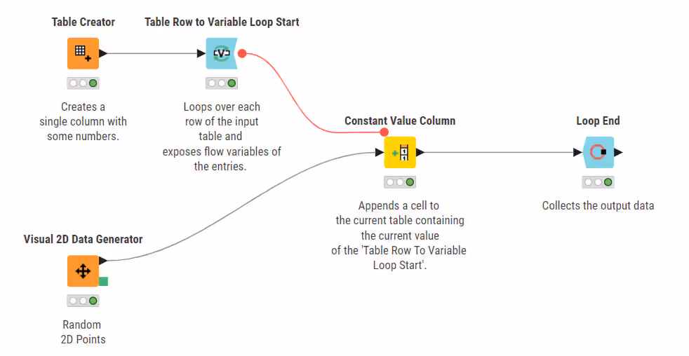
Similarly to the Table Row to Variable node, the Table Row to Variable Loop Start node transforms the row of a table to a set of variables that have as name the column name and as value the corresponding value in the current row. It loops over each row of the input table and exposes the flow variables obtained to the loop body. In this example, one of the flow variables obtained is used to overwrite the column value parameter setting of the Constant Value Column node, which appends a cell containing the current value to the current table.
If you create more than one flow variable with the same name, only the last saved value of that variable will be retained because it overwrites the previous one. This happens easily when loop nodes are involved.
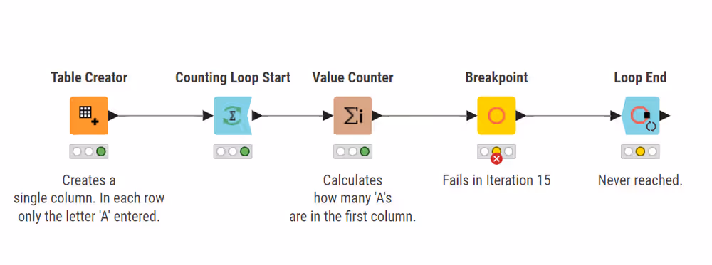
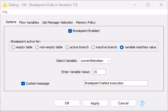
Breakpoint node
In the node repository, under Workflow Control → Loop Support, Breakpoint node is also available. You can use it to halt execution when certain conditions are met. The example below shows the use of this node to impair the execution of the loop when the input flow variable corresponding to the value of the customer segment is equal to three. You can also configure the Breakpoint node to halt execution when it receives as input an empty table, and active or inactive branch. You can also set a Custom message to be shown if the Breakpoint node condition is met. This workflow is also available on KNIME Hub.
IF and CASE Switches
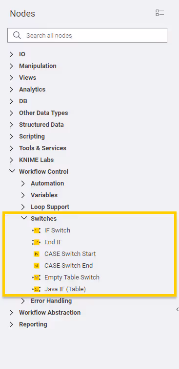
In case you need to perform different operations on different groups of the data, you can use a logic which is able to split the workflow into branches. The IF and CASE nodes available in KNIME Analytics Platform have this function. The nodes for IF and CASE switches are located in the node repository under Workflow Control → Switches.
IF Switch node
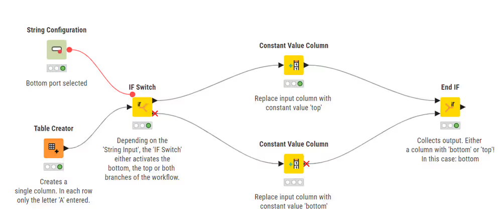
The IF Switch node creates two branches in the workflow which can be alternatively activated or deactivated. This means, the nodes in the active branch or branches are executed and the nodes in the inactive one are not. In the node configuration dialog you can define the active branch either manually, or it can be dynamically controlled by a condition, through a flow variable.
The example below, also available on KNIME Hub, loops over an IF Switch to read in data row by row, to categorize the customers based on their call activity. When the loop is finished, the rows are concatenated back into the same table.
In this workflow, the IF Switch node has both data and flow variable input. The flow variable, created with the String Input node, defines the active branch. The data are then handled in the active branch.
Defining the active port via a flow variable
The Select active port option is located in the Options tab of the IF Switch node configuration dialog. Here, you can manually select either both, bottom or top, to define the active branch. However, you can also use a flow variable to overwrite the active port option.
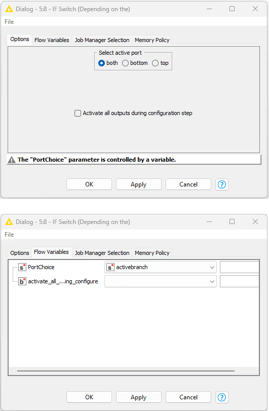
First, you need to create a suitable flow variable. Since you need to use it to overwrite the Select active port option of the IF Switch node, you have to assign to it a string value equal to either both, bottom or top.
In the previous example, this flow variable is created using a String Input node which allows to manually set the output flow variable to one of the suitable string values.
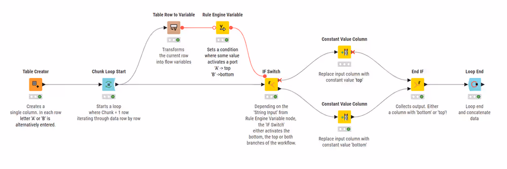
Another possibility is to automatically activate a branch according to some set condition, within a loop. In the example shown below and available on KNIME Hub, a loop is performed row by row over some data. Each row is then transformed in flow variables and, depending on the value of a specific column the IF Switch ports are activated.
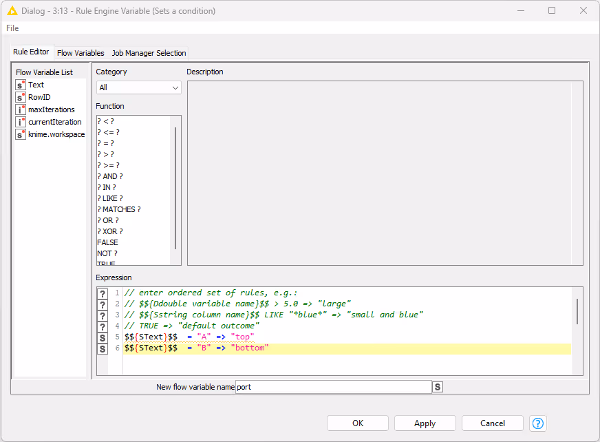
The Rule Engine Variable node configuration dialog is shown below. Here the antecedents are defined using the flow variables and functions available while the consequent of a true condition is assigned with the => sign. The default outcome, i.e. the value assigned to all cases for which none of the rules is true, is defined using the syntax TRUE => "default outcome".
CASE Switch Data (Start) node
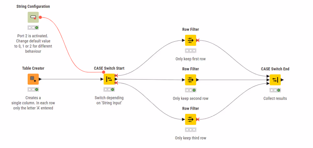
With the CASE Switch Data (Start) node you can activate one of three branches in a workflow. Similar to the IF Switch node, this can be either done manually or by using a condition.
Once the execution has finished, the tables resulting from the branches can be concatenated by using an End IF node or CASE Switch Data (End) node.
An example, similar to the one of IF Switch Data node, is shown here and is also available on KNIME Hub.
Note that when using the CASE Switch, the possible values for the active output port are
0for the top,1for the middle, and2for the bottom output port. That said, the functionality is similar, but the flow variable values are different.
Error handling
Different type of errors, such as a failing connection to a remote service, the invocation of a not accessible database, and so on, can occur when executing a workflow. To handle them you can use the Try-Catch enclosures. The Try part executes some node(s). If the execution fails, the Catch branch with error handling is activated. Otherwise the Default branch is executed. At the end of the Try-Catch enclosure, the results from either the successful or failed execution are collected.
An example of a Try-Catch enclosure is shown here below and it is available on KNIME Hub.
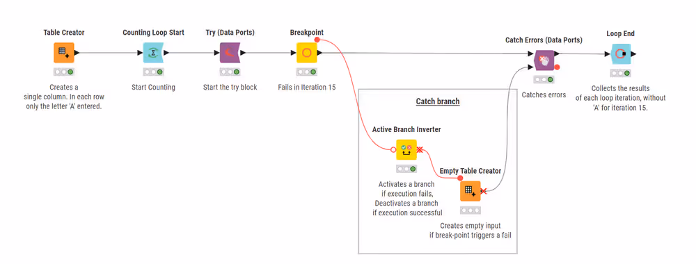
In the workflow, the Try (Data Ports) node begins the enclosure, followed by the Breakpoint node. The Breakpoint node is set to fail at the fifteenth iteration. Here, if execution of the Try part fails the Catch branch is executed.
The Active Branch Inverter node begins the Catch branch for error handling. This node makes an inactive branch active and active branch inactive:
- It activates a branch in the event that execution fails
- It deactivates a branch if execution is successful
The Catch Errors (Data Ports) node closes the Try-Catch enclosure:
- If execution is successful, the output of the node is the output from the Default branch. Therefore, the Default branch must be connected to the top input port of the Catch Errors (Data Ports) node.
- If execution fails, the output of the enclosure comes from the Catch branch, which must be connected to the bottom input port of the Catch Errors (Data Ports) node. The reasons for the failure are then reported in the flow variable output of the Catch Errors (Data Ports) node.
Besides data tables, the Try part can also be started with a flow variable, using the Try (Variable Ports) node instead.
One of the following four alternatives is available to end the Try-Catch loop:
- Catch Errors (Data Ports)
- Catch Errors (Var Ports) if the outputs of the Catch and Default branches are flow variables
- Catch Errors (Generic Ports) for models
- Catch Errors (DB Ports) for database queries.
You will find the nodes for a Try-Catch enclosure in the node repository by navigating to Workflow Control → Error Handling.