
IF and CASE Switches
If you need to perform different operations on different groups of the data, you can use logic that splits the workflow into two branches. Depending on the logic, either one or both branches are then activated. The IF and CASE nodes in Knime provide this functionality. The nodes for IF and CASE switches are located in the node repository under Workflow Control → Switches.
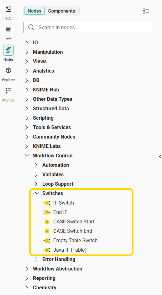
IF Switch node
The IF Switch node creates two branches in the workflow which can be alternatively activated or deactivated. This means that the nodes in the active branch or branches are executed and the nodes in the inactive one are not. In the node configuration dialog, define the active branch either manually, or dynamically control it with a condition through a flow variable.
The example below, also available on Knime Community Hub, demonstrates how to use an IF Switch to control which branch of a workflow is active.
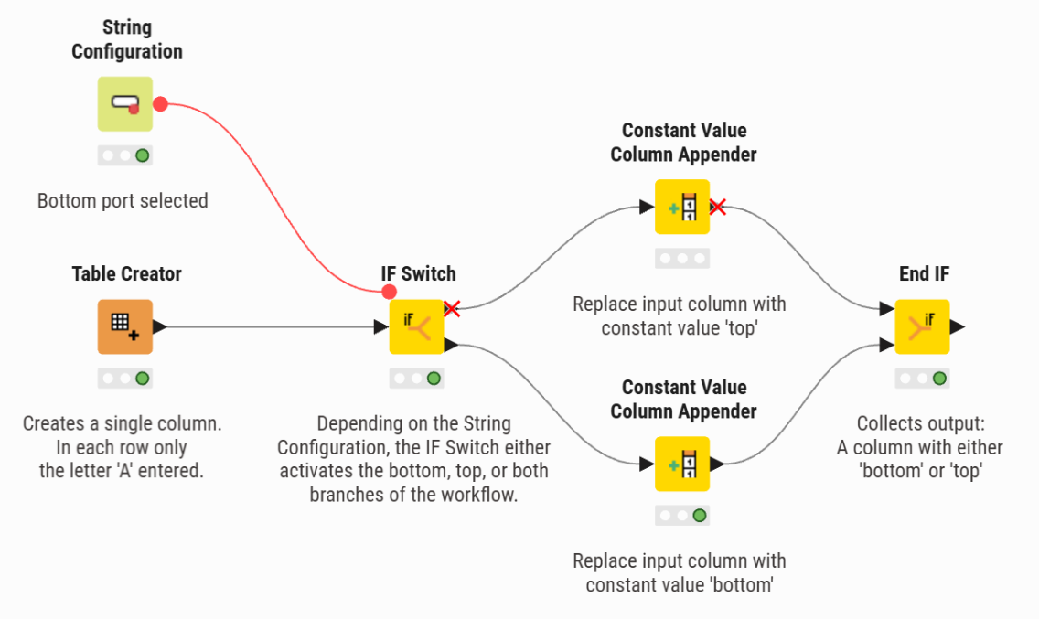
In this workflow, the IF Switch node has both a data input and a flow variable input. The flow variable, created with the String Configuration node, defines the active branch depending on whether it takes on the value top, bottom, or both. The data is then handled in the active branch. The End IF node closes the switch by collecting the output of the active branch.
Defining the active port via a flow variable
In the configuration window of the IF Switch node, the Active port option defines which branch is active. Set this manually by selecting Both, Top, or Bottom. You can also use a flow variable to overwrite the active port option.
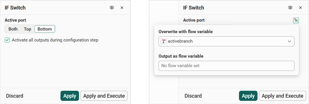
First, create a suitable flow variable. To overwrite the Active port option of the IF Switch node, assign it a string value equal to either both, bottom, or top.
In the previous example, this flow variable is created using a String Configuration node, which lets you manually set the output flow variable to one of the suitable string values.
Another possibility is to automatically activate a branch according to a set condition within a loop. In the example shown below, also available on Knime Community Hub, a loop processes the input data row by row. Each row is then transformed into a flow variable and, depending on the value in the column, the respective IF Switch port is activated.
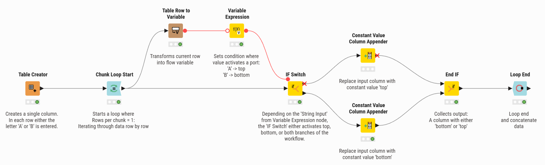
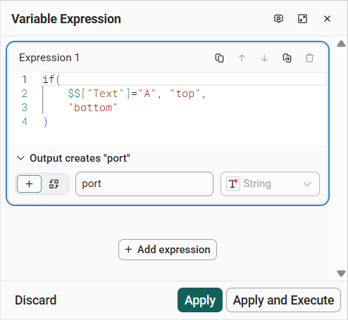
The Variable Expression node configuration dialog is shown below. Here, an IF condition is defined to derive the value for the port flow variable. The IF condition checks the value in column Text; if the value equals A, the flow variable is assigned as top, otherwise it is bottom (the default outcome).
CASE Switch Start node
With the CASE Switch Start node, you can activate one of several branches in a workflow. By default, two output ports are available. To increase the number of ports, click the plus in the bottom right corner of the node. This lets you switch between more than two branches. Similar to the IF Switch node, branch selection can be done either manually or by using a condition.
When you add the CASE Switch Start node to the workflow editor, add an input port type first. The CASE Switch nodes support several port types, such as data table, flow variable, and DB connection, and more.
Once the execution has finished, the tables resulting from the branches can be concatenated by using a CASE Switch End node. Make sure the number of input ports of the CASE Switch End node matches the number of branches defined in the workflow.
An example, similar to the one for the IF Switch node, is shown here and is also available on Knime Community Hub.
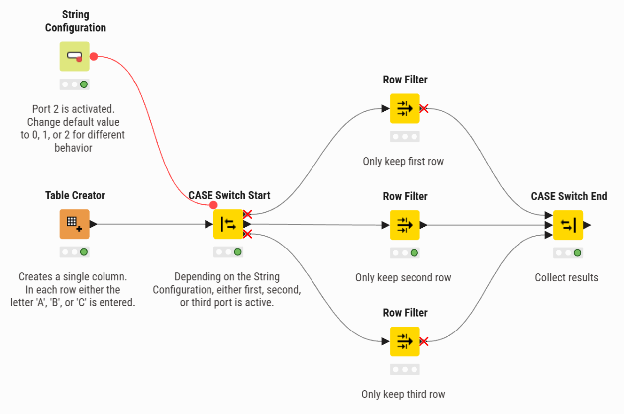
When using the CASE Switch Start node, the possible values for the active output port are defined by indices:
0for the topmost port,1for the following, then2, and so on. The functionality is similar, but the flow variable values are different.